

Leadsintec Group, The most Reliable, Rapid, One-Stop electronic manufacturer


Leadsintec Group, The most Reliable, Rapid, One-Stop electronic manufacturer

 Precision in Every Circuit.
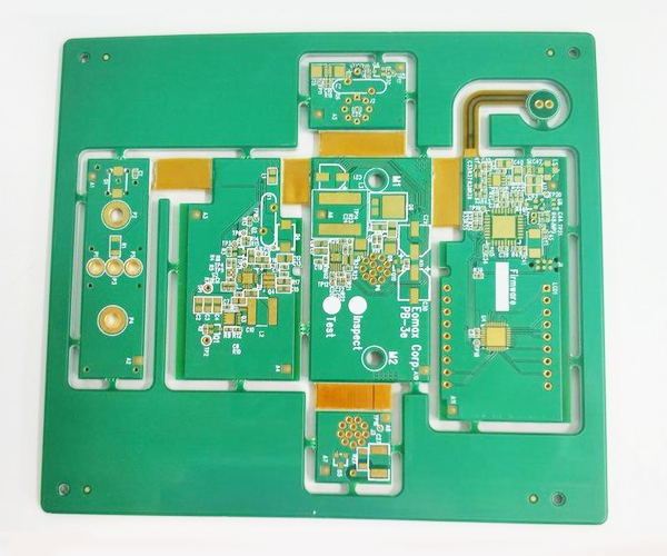
Rigid-Flex PCBs combine the best features of both rigid and flexible circuit boards, offering a hybrid structure that integrates rigid sections for stability and flexible areas for dynamic movement. This combination allows for three-dimensional configurations, reducing space requirements and improving mechanical performance in complex electronic assemblies. The ability to fold or bend flexible sections while maintaining solid, reliable connections makes rigid-flex PCBs ideal for compact and high-performance devices.
Their superior design flexibility, durability, and reliability under stress make them widely used in aerospace, military, medical, and consumer electronics where space constraints and dynamic environments are common. Rigid-Flex PCBs reduce connector use, lower assembly costs, and improve signal integrity, making them an advanced solution for applications demanding both flexibility and structural integrity.
Rigid-Flex PCBs combine the advantages of both rigid and flexible circuit boards, offering a hybrid design that incorporates rigid sections for structural stability and flexible areas for movement and compactness. This technology allows for more complex and space-efficient designs, making it ideal for products that need to withstand mechanical stress while maintaining high performance. By eliminating the need for connectors between rigid and flexible components, Rigid-Flex PCBs improve signal integrity, reduce assembly costs, and enhance reliability. They are commonly used in industries such as aerospace, medical devices, telecommunications, and consumer electronics, where compactness, durability, and performance are crucial.
Number of manufacturing layers: 1-48 layers
Number of SMT lines: 8 high-speed SMT mating lines
SMT daily production capacity: More than 50 million points
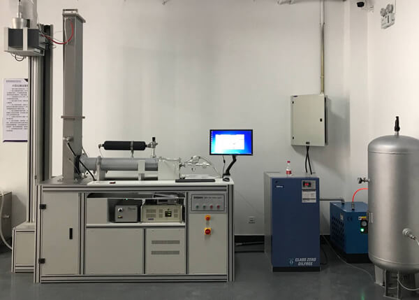
Inspection equipment: X-RAY tester, first piece tester, AOI automatic optical tester, ICT tester, BGA rework station
Mounting speed: CHIP component mounting speed (optimal conditions) 0.036S/chip
Minimum package: 0201, accuracy up to +0.04mm
Minimum device accuracy: PLCC, QFP, BGA, CSP and other devices can be pasted, pin spacing up to +0.04mm
18 years of pcb manufacturing experience Authoritative manufacturing team
Adoption of advanced technology and manufacturing equipment Perfect production system Fast turnaround
Mature ISO9001/IATF16949 quality management system. Perfect ERP and MaS order management system.
Professional cost control engineers Cooperation with many raw material companies.
Free DFM inspection of PCB files and BOMs. PCB engineering evaluation and advice.
Specialized in medical, automotive, consumer electronics, new energy pcb. Serving global enterprises
Rigid-Flex PCB designs combine both rigid and flexible board technologies. In most rigid-flex boards, flexible circuit substrate layers are attached to one or more rigid boards internally, externally, or both, depending on the design specifications of the application. Typically, rigid-flex printed circuit boards are produced with a flexible polyimide material on a copper-clad substrate that is attached to a rigid board. This combination allows rigid-flex PCBs to have more application scenarios, such as electronic devices, advanced aircraft-mounted weapon guidance systems, military and avionics manufacturing, and more.
Rigid-flex pcb offer a number of advantages, including light weight, ease of assembly and repair, and enhanced reliability, performance, and flexibility of electronic devices. These and more will be discussed later:
➤ Compact Size
Electronic devices are becoming smaller and more flexible. The versatility of rigid-flexible PCBs allows them to be bent and folded to fit smaller devices and properly connect miniature components. This miniaturization also makes them lightweight.
➤ Increased Reliability
Since there are fewer solder joints and board-to-board connectors, there is less likelihood of connection impedance. In addition, the attached rigid and flexible layers are firmly and reliably connected, thus ensuring fewer circuit failures.
➤ Space saving
Since the flexible substrate has built-in interconnection circuits, there is more space for wiring on the rigid-flexible PCB. This makes the boards suitable for compact design applications as they do not provide much space for wiring harnesses and high profile connectors.
➤ Reduced Costs
Although rigid-flex boards are more expensive than regular rigid PCBs, they are more cost-effective in terms of assembly costs. Because of their smaller size and fewer connections, rigid-flex PCBs require less material to assemble. Fewer parts and connector assemblies reduce the cost of purchasing and assembling the final product and increase revenue. This means that Rigid-Flex PCBs significantly reduce overall manufacturing costs for assembly and logistics.
➤ Easy to Test
The interconnected subcircuits of Rigid-Flex PCBs can be easily subjected to automated testing. This testing allows manufacturers to eliminate connectivity issues prior to component assembly, preventing unnecessary waste and expense.
➤ Design Flexibility
3D design and multi-layer flexible circuits make rigid-flex PCBs highly flexible and able to be installed into small devices. This way, devices are no longer limited to a specific PCB design like rigid boards, as rigid-flex boards have an impressive bend radius and can therefore be bent into a variety of applications.
➤ Resistant to high temperatures and harsh conditions
This type of PCB can withstand high temperatures because of the use of polyimides with high thermal stability in its design. In addition, by combining the best characteristics of both rigid and flexible boards, it has considerable resistance to radiation, harmful oils and chemicals, as well as extreme shock and vibration, and other harsh industrial conditions. This makes it ideal for equipment that may be subjected to excessive movement and vibration during use.
The special advantages of rigid-flex pcb make them widely used in industrial, commercial and household fields. In addition, they are also popular in the medical, aerospace, communications, automotive, and military fields.
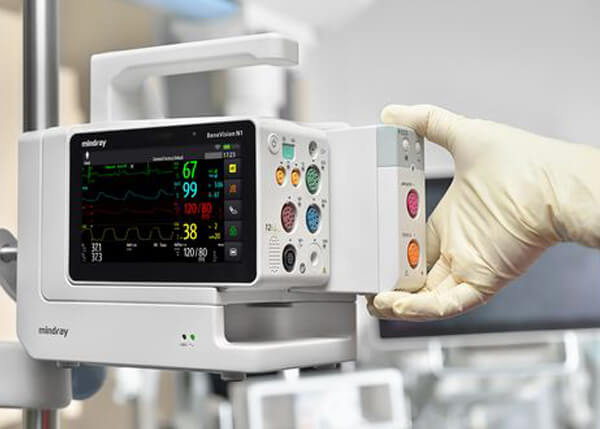
Medical: Used in pacemakers, cochlear implants, handheld monitors, imaging equipment, drug delivery systems, wireless controllers and other devices.
Aerospace: This application produces equipment such as radar equipment, GPS, radio communication systems, control tower systems, sensors, noise and vibration test systems, motion sensors, and environmental and climate test chambers.
Telecommunications: This field has base stations, handheld devices, communication satellites, wireless communication systems, signal processing systems, transmission media, routers and servers, and online signal extension systems.
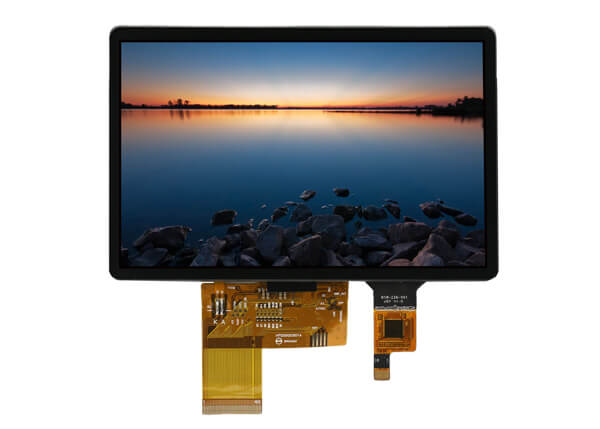
Consumer Appliances: This is a common application for rigid-flex pcb, commonly found in ovens, TV remote controls, washing systems, lighting systems, solar energy systems, UV water purifiers, electronic irons, and more.
Automotive: The industry is no exception, applying rigid-flex to electronic control modules, transmission controls, LCDs, comfort control units, and products such as air conditioning, music, traction control, entertainment and navigation systems.
Military: Rigid-flex PCBs have important applications in the production of weapon guidance systems, communication systems, GPS, aircraft missile launch detectors, and surveillance or tracking systems.
Manufacturing: In this field, rigid-flex PCBs are used in test equipment, electrical switches, industrial automation systems, control pcb, industrial air-conditioning and CCTV monitoring systems.

Producing a reliable rigid-flex PCB requires advanced manufacturing techniques and processes. Here is an overview of rigid-flex fabrication:
1. Materials Preparation
The process starts with raw rigid and flexible core materials being prepared. The materials are cleaned, coated, and conditioned to optimize adhesion and processing performance.
2. Imaging
The individual inner and outer layers are imaged with the conductive pattern using lithography and etching processes. This forms the traces, pads, and features on each layer.
3. Hole Formation
Holes are drilled or punched through the core layers. This includes component holes, tooling holes, and through vias between layers. The holes are plated with copper to form the vertical interconnects.
4. Lamination
The rigid and flexible core layers are precisely aligned and bonded using high temperature and pressure. The bond line between materials is critical to performance. Advanced adhesives are used.
5. Outer Layer Imaging
After lamination, the outer layer traces and features are imaged using lithography and etching. This completes the conductive patterning on the PCB.
6. Solder Mask and Finish
Solder mask is applied to exposed copper surfaces. The edges of pads and traces are exposed. The PCB surface is finished with treatments like ENIG, immersion tin, or OSP.
7. Singulation
The large panel is precision routed to separate into individual PCBs. Rigid-flex PCBs often have complex board shapes.
8. Testing
Each completed PCB goes through electrical testing and inspection to verify function and workmanship. Automated optical inspection checks feature accuracy.
9. Assembly
Components are mounted on the rigid portions using soldering or adhesive attachment. The PCB can then be dynamically flexed into the 3D shape as required.
Rigid-flex PCB fabrication requires expertise in advanced processes like:
▶ Surface preparation and adhesion promotion
▶ High-accuracy imaging and pattern transfer
▶ Controlled lamination of dissimilar materials
▶ Mitigation of thermal and mechanical process stresses
▶ Precise techniques for routing, drilling, and hole plating
▶ DFM techniques for optimizing manufacturability
| Feature | Capability |
| Quality Grade | Standard IPC 2 |
| Number of Layers | 2 – 26layers |
| Order Quantity | 1pc – 10000+pcs |
| Build Time | 2days – 4weeks |
| Material | FR4 |
| Board Size | Min 6mm x 6mm |
| Max 457mm x 610mm | |
| Board Thickness | 0.6mm – 5.0mm |
| Copper Weight (Finished) | 0.5oz – 2.0oz |
| Min Tracing/Spacing | 3mil/3mil |
| Solder Mask Sides | As per the file |
| Solder Mask Color | Green, White, Blue, Black, Red, Yellow |
| Silkscreen Sides | As per the file |
| Silkscreen Color | White, Black, Yellow |
| Surface Finish | HASL – Hot air solder leveling |
| Lead – free HASL – RoHS | |
| ENIG – RoHS | |
| Min Annular Ring | 4mil |
| Min Drilling Hole Diameter | 8mil |
| Impedance control | ±10% |
| Other Techniques | HDI |
| Gold fingers |
We're pleased to be welcoming customers to join us.
Thank you for your interest in solar energy! Whether you're curious about transitioning to solar power for your home or business.

Contact us today via the form below social Share and let's take the first step.


As the Best Rigid Flex PCB Manufacturer, Leadsint Group delivers cutting-edge hybrid circuit solutions that blend the stability of rigid boards with the adaptability of flexible circuits. Serving as a trusted Rigid Flex PCB Supplier, we empower industries worldwide with compact, reliable, and high-performance PCBs designed for the most demanding applications. With over 18 years of expertise, ISO9001 and IATF16949 certifications, and state-of-the-art facilities, we ensure precision, speed, and cost-efficiency in every project.
A Rigid Flex PCB is an innovative hybrid circuit board that integrates rigid FR4 substrates for structural support with flexible polyimide layers for dynamic bending and folding. This seamless combination eliminates the need for bulky connectors, enabling three-dimensional designs that save space, enhance signal integrity, and withstand extreme conditions like vibration, shock, and high temperatures.
As the leading Rigid Flex PCB Supplier, we specialize in crafting these boards to meet your exact specifications, supporting 2-26 layers, minimum trace/spacing of 3mil/3mil, and advanced features like HDI and impedance control (±10%).
Our free DFM (Design for Manufacturability) reviews ensure your designs are optimized from the start.
As a premier Rigid Flex PCB Supplier, we power mission-critical innovations in diverse sectors:
From prototypes to high-volume runs (1pc to 10,000+), we scale to your needs.
At Leadsint Group, the Best Rigid Flex PCB Manufacturer leverages 8 advanced SMT lines with >50 million points/day capacity, X-RAY/AOI inspection, and mounting accuracy of +0.04mm for packages down to 0201. Key specs include:
|
Feature |
Specification |
|
Layers |
2-26 |
|
Board Size |
Min: 6mm x 6mm / Max: 457mm x 610mm |
|
Thickness |
0.6mm - 5.0mm |
|
Copper Weight |
0.5oz - 2.0oz |
|
Min Trace/Spacing |
3mil / 3mil |
|
Min Drilling |
8mil |
|
Surface Finish |
HASL, Lead-Free HASL, ENIG, Immersion Tin, OSP |
|
Build Time |
2 days - 4 weeks |
|
Quality Standard |
IPC Class 2 |
We handle complex processes like precise lamination, controlled-depth drilling, and stress-relief routing to guarantee flawless performance.
Ready to transform your ideas into reality? Contact our team today for a quote or consultation. As the Best Rigid Flex PCB Manufacturer and reliable Supplier, Leadsint Group is your gateway to superior hybrid PCB solutions.

