

Shenzhen Leadsintec Technology Co., Ltd


Shenzhen Leadsintec Technology Co., Ltd

 Precision in Every Circuit.
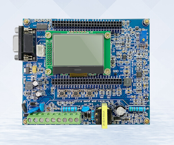
High-frequency PCBs are designed to operate effectively at high signal frequencies, often exceeding 1 GHz, where traditional PCBs may struggle with signal integrity and loss. These boards are made from specialized materials that ensure low signal loss, minimal interference, and high-speed performance, making them ideal for advanced applications in telecommunications, aerospace, and high-speed data transmission systems.
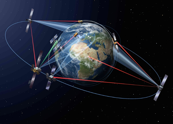
High-frequency PCBs are critical in industries where precision, fast signal transmission, and low attenuation are necessary, enabling the development of next-generation communication technologies, radar systems, and satellite communications.
High-frequency PCBs are designed to handle high-speed signals and operate effectively at frequencies typically above 1 GHz. These specialized circuit boards are made using advanced materials such as PTFE (Polytetrafluoroethylene) or ceramic composites, which help minimize signal loss, reduce interference, and maintain signal integrity over long distances. High-frequency PCBs are essential in applications such as telecommunications, radar systems, satellite communications, and high-speed data transmission, where performance, speed, and reliability are crucial. By offering low dielectric constants and stable electrical characteristics, high-frequency PCBs ensure optimal functionality in demanding environments, enabling the development of advanced communication and electronic systems.
Number of manufacturing layers: 1-48 layers
Number of SMT lines: 8 high-speed SMT mating lines
SMT daily production capacity: More than 50 million points
Inspection equipment: X-RAY tester, first piece tester, AOI automatic optical tester, ICT tester, BGA rework station
Mounting speed: CHIP component mounting speed (optimal conditions) 0.036S/chip
Minimum package: 0201, accuracy up to +0.04mm
Minimum device accuracy: PLCC, QFP, BGA, CSP and other devices can be pasted, pin spacing up to +0.04mm
18 years of pcb manufacturing experience Authoritative manufacturing team
Adoption of advanced technology and manufacturing equipment Perfect production system Fast turnaround
Mature ISO9001/IATF16949 quality management system. Perfect ERP and MaS order management system.
Professional cost control engineers Cooperation with many raw material companies.
Free DFM inspection of PCB files and BOMs. PCB engineering evaluation and advice.
Specialized in medical, automotive, consumer electronics, new energy pcb. Serving global enterprises
High-frequency PCB board refers to a printed circuit board above 1GHz. This definition may be different in the industry. Its physical performance, accuracy, and technical parameters are very high. They are often used in the fields of communication systems, car ADAS systems, satellite communication systems, and radio systems.
High-frequency PCB is a circuit board for high -frequency signal transmission. It has the following characteristics:
1. Low loss: High-frequency PCB uses better materials and special process design, which can reduce the loss of signals during transmission and maintain lower signal attenuation.
2. Low noise: Special design and shielding technology adopted by high-frequency PCB can reduce the generation and dissemination of noise, and provide clean signal output.
3. Good impedance matching: High -frequency PCB can achieve effective impedance matching with other high-frequency devices through accurate design and debugging to improve the efficiency of signal transmission.
4. Strong anti-interference ability: High-frequency PCB has good anti-interference ability, can work normally in a complex electromagnetic environment, and reduce the impact of external interference on signals.
5. The dielectric constant is small and stable: Generally speaking, the smaller the dielectric constant, the better because the square root of the signal transmission rate is the opposite of the square root of the material of the material. At the same time, the medium consumption requirements are small because this will mainly affect the quality of signal transmission.
6. Thermal expansion coefficient is consistent with copper foil: If the thermal expansion coefficient is not synchronized, it will cause copper foil to be separated during hot and cold.
7. Excellent heat resistance, chemical resistance, impact strength and separation strength: These characteristics ensure the stability and reliability of high-frequency PCB in harsh environments.

We manufacture high-frequency PCBs with frequency typically in the range from 500MHz to 2GHz.
| Feature | Capability |
| Quality Grade | 3.00 +/- .04. |
| Number of Layers | 2 – 42layers |
| Order Quantity | 1pc – 10000+pcs |
| Build Time | 2days – 5weeks |
| Material | RO4003C, RO4350B, Ro3003, Ro3010, RT5880 |
| PP | Rogers 4450F, Domestic-(25FR), Domestic-(RF-27), Domestic-(6700) |
| Board Size | Min 6mm x 6mm | Max 457mm x 610mm |
| Board Thickness | 0.4mm – 5.0mm |
| Copper Weight(Finished) | 0.5oz – 2.oz |
| Min Tracing/Spacing | 3mil/3mil |
| Solder Mask Sides | As per the file |
| Solder Mask Color | Green, White, Blue, Black, Red, Yellow |
| Silkscreen Sides | As per the file |
| Silkscreen Color | White, Black, Yellow |
| Surface Finish | Electroless nickel/immersion gold (ENIG) – RoHS |
| Immersion silver – RoHS | |
| Immersion tin – RoHS | |
| Organic solderability preservatives – RoHS | |
| Min Annular Ring | 4mil |
| Min Drilling Hole Diameter | 6mil |
| Impedance tolerance | ±10% |
| Other Techniques | Peelable solder mask |
| Gold fingers | |
| Carbon oil | |
| Countersink holes |
We're pleased to be welcoming customers to join us.
Thank you for your interest in solar energy! Whether you're curious about transitioning to solar power for your home or business.

Contact us today via the form below social Share and let's take the first step.


